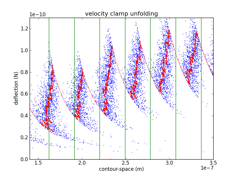
I've been spending some time comparing my force spectroscopy data with Marisa's, and the main problem has been normalizing the data collected using different systems. Marisa runs experiments using some home-grown LabVIEW software, which saves the data in IGOR binary wave (IBW) files. From my point of view, this is not the best approach, but it has been stable over the time we've been running experiments.
I run my own experiments using my own code based on pyafm, saving the data in HDF5 files. I think this approach is much stronger, but it has been a bit of a moving target, and I've spent a good deal of my time working on the framework instead of running experiments.
Both approaches save the digitized voltages that we read/write during an experiment, but other constants and calibration terms are not always recorded. My pyafm-based software has been gradually getting better in this regard, especially since I moved to h5config-based initialization. Anyhow, here's a quick runthough of all the important terms.
For the TL;DR crowd, crunch.py is my Python module that crunches your input and prints out all the intermediate constants discussed below. To use it on your own data, you'll probably have to tweak the bits that read in the data to use your own format.
Calibrating the piezo
Calibration grid
We control the surface-tip distance by driving a piezo tube. We want to know the correspondence between the driving voltage and the piezo position, so we calibrate the piezo by imaging a sample with square pits of a known depth.
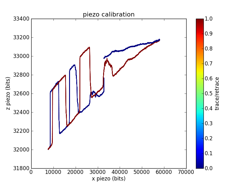
In this trace, I swept the position across most of the range of my 16-bit DAC. For each position, I adjusted the position until the measured cantilever deflection crossed a setpoint. This gives the voltage required to reach the surface as a function of . You can see the 200 nm deep square pits, as well as a reasonable amount of / crosstalk.
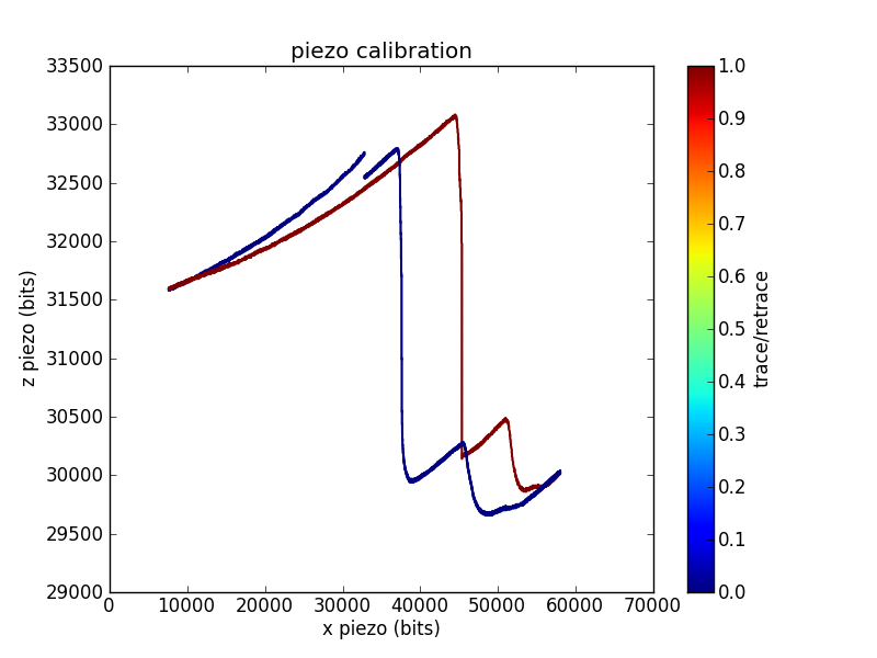
Sometimes grid calibrations are even less convincing than the example shown above. For example, I have traces with odd shoulders on the sides of the pits:
This is one of the better piezo calibration images I aquired for the piezo used in the pull below, so I'll use numbers from the funky imaging for the remainder of this analysis. This piezo has less / range than the one used to measure the first calibration trace, which is why I was unable to aquire a full pit (or pits).
The calibration constant is the number of bits per depth meter:
Related conversion factors are
This is roughly in the ballpark of our piezo (serial number 2253E) which is spec'd at 8.96 nm/V along the axis, which comes out to V/m.
Laser interference
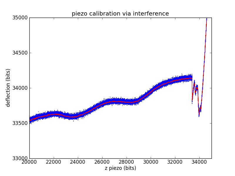
Another way to ballpark a piezo calibration that is much closer to a force spectroscopy pull is to use the laser interference pattern as a standard length. The laser for our microscope has a wavelength of 670 nm. We'll assume a geometric gain of
Measuring the length of an interference wave in bits then gives a standard equivalent to the known-depth pits of the calibration grid.
The other piezo calibration parameters are found exactly as in the calibration grid case.
which is fairly close to both the spec'd value and grid calibration values.
Calibrating the photodiode
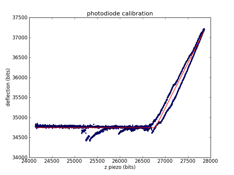
During experiments, we measure cantilever deflection via the top and bottom segments of a photodiode. We need to convert this deflection voltage into a deflection distance, so we'll use the already-calibrated piezo. When the tip is in contact with the surface, we can move the surface a known distance (using the piezo) and record the change in deflection.
The calibration constant is the number of diode bits per piezo bit.
Related conversion factors are
Calibrating the cantilever spring constant
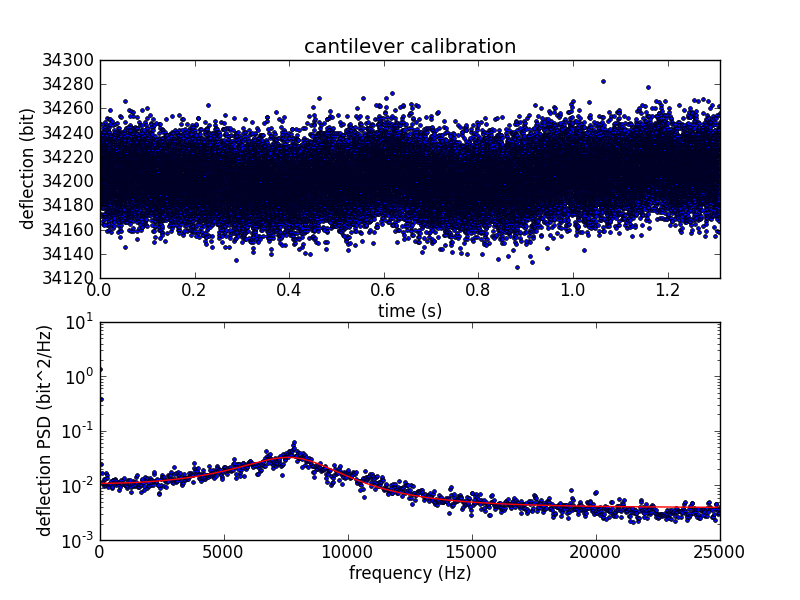
To convert cantilever tip deflection to force, we need to know the spring constant of the cantilever. After bumping the surface, we move away from the surface and measure the cantilever's thermal vibration. We use the vibration data to calculate the spring constant using the equipartition theorem.
The deflection variance is measured in frequency space, where the power spectral density (PSD) is fitted to the expected PSD of a damped harmonic oscillator.
Analyzing a velocity-clamp pull
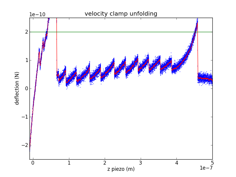
The raw data from a velocity-clamp pull is an array of output voltages used to sweep the piezo (moving the surface away from the cantilever tip) and an array of input voltages from the photodiode (measuring cantilever deflection). There are a number of interesting questions you can ask about such data, so I'll break this up into a few steps. Lets call the raw piezo data (in bits) , with the contact-kink located at . Call the raw deflection data (also in bits) , with the contact-kink located at .
Piezo displacement
Using the piezo calibration parameters, we can calculate the raw piezo position using
measured in meters.
Surface contact region
During the initial portion of a velocity clamp pull, the cantilever tip is still in contact with the surface. This allows you to repeat the photodiode calibration, avoiding problems due to drift in laser alignment or other geometric issues. This gives a new set of diode calibration parameters and (it is unlikely that has changed, but it's easy to rework the following arguments to include if you feel that it might have changed).
Tension
We can use the new photodiode calibration and the cantilever's spring constant to calculate the force from the Hookean cantilever:
Protein extension
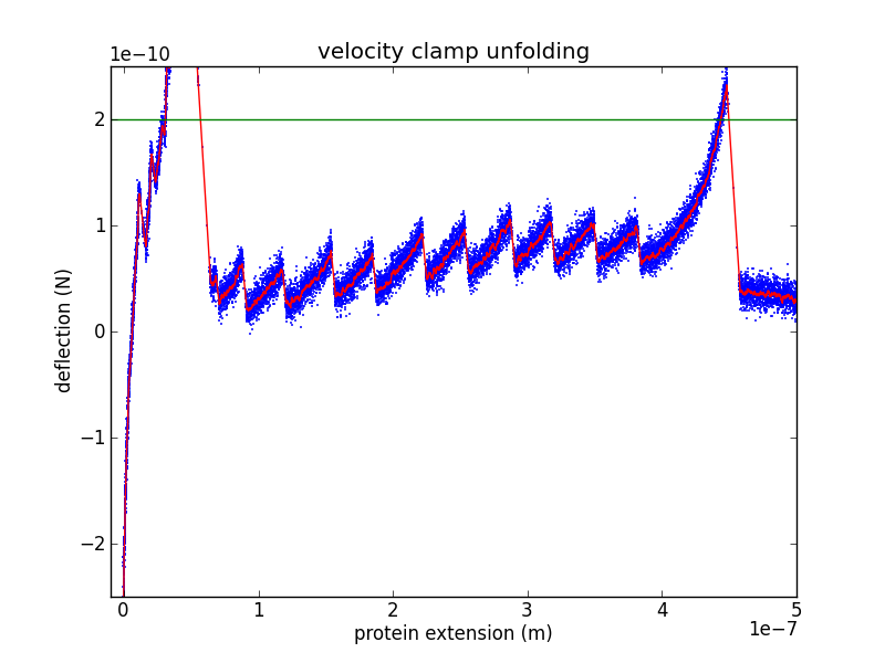
As the piezo pulls on the cantilever/protein system, some of the increased extension is due to protein extension and the rest is due to cantilever extension. We can use Hooke's law to remove the cantilever extension, leaving only protein extension:
Contour-space
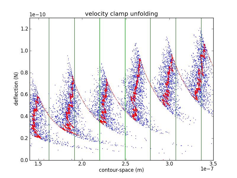
In order to confirm the piezo calibration, we look at changes in the unfolded contour length due to domain unfolding (). There have been a number of studies of titin I27, starting with Carrion-Vazquez et al., that show an contour length increase of 28.1 ± 0.17 nm. Rather than fitting each loading region with a worm-like chain (WLC) or other polymer model, it is easier to calculate by converting the abscissa to contour-length space (following Puchner et al.). While the WLC is commonly used, Puchner gets better fits using the freely rotating chain (FRC) model.
In crunch.py, I use either Bustamante's formula (WLC) or Livadaru's equation 49 (FRC) to calculate the contour length of a particular force/distance pair.
As you can see from the figure, my curves are spaced a bit too far appart. Because the contour length depends as well as , it depends on the cantilever calibration (via , , and ) as well as the piezo calibration (via ). This makes adjusting calibration parameters in an attempt to match your with previously determined values a bit awkward. However, it is likely that my cantilever calibration is too blame. If we use the value of from the interference measurement we get
Which is still a bit too wide, but is much closer.
